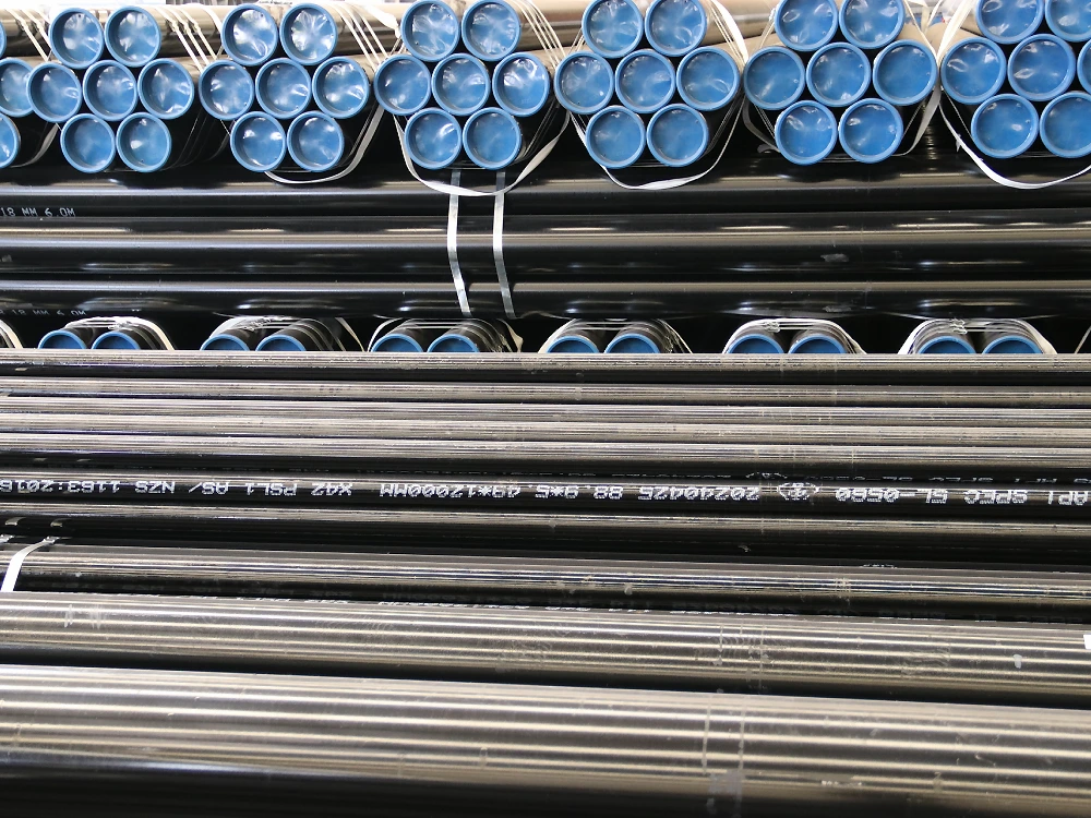
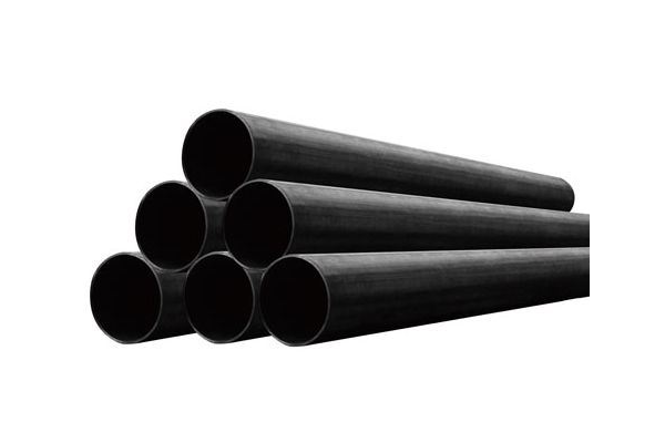
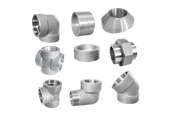
EN 10219-UNIASEN-PILING PIPE

EN 10219

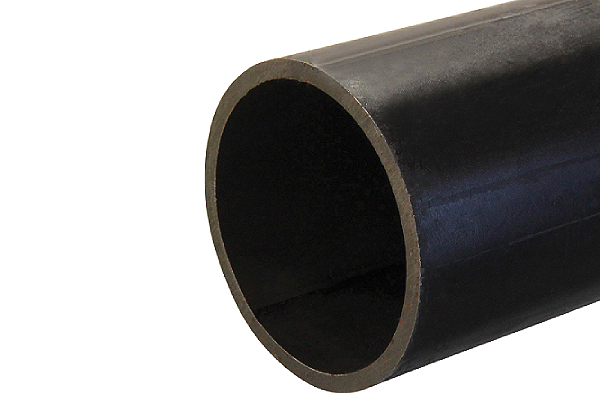
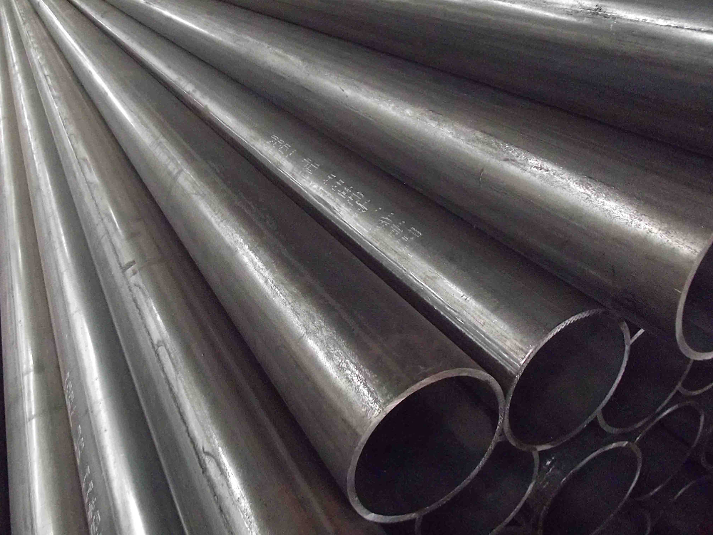
EN 10219 specifies the requirements for cold-formed welded structural hollow sections of cold-formed, non-alloy, and fine-grain steel tubes.

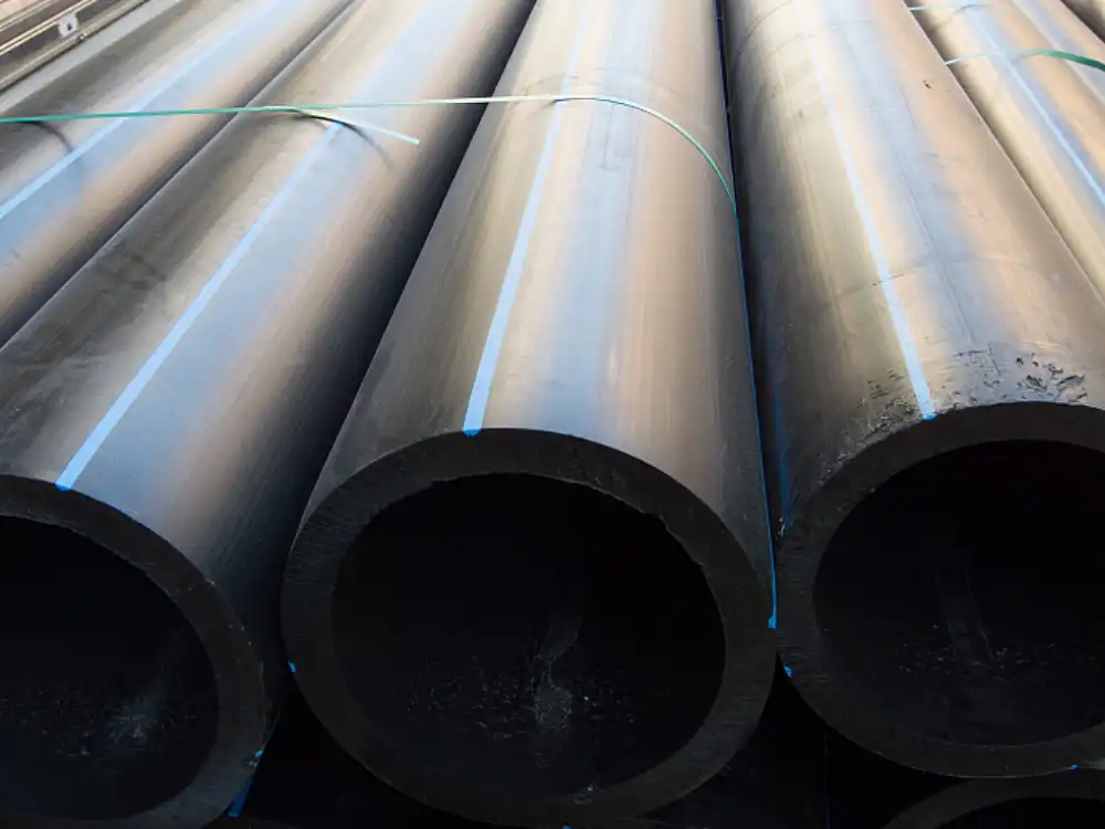
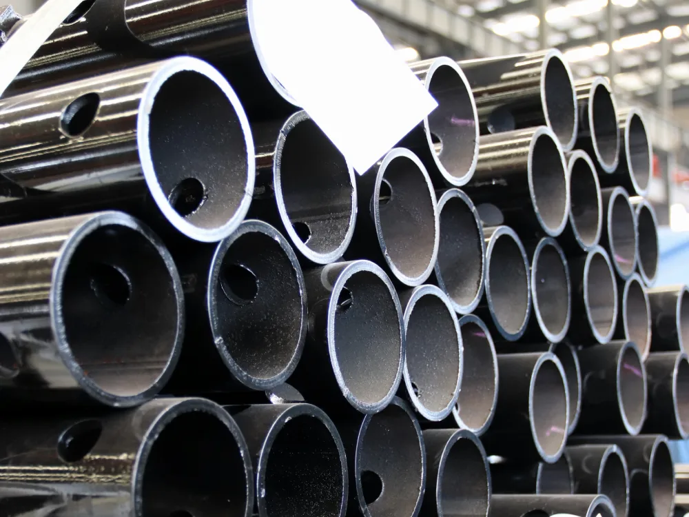
The standard is divided into 3 parts. The first part includes the technical delivery requirements of EN 10219 tubes. Part 1 covers the tolerances, dimensions, and cross-sectional properties of EN 10219 tubes. Part 3 is the technical delivery conditions of EN 10219 tubes for high-strength and weathering steel.

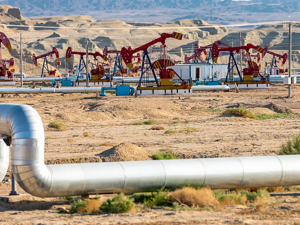
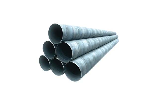
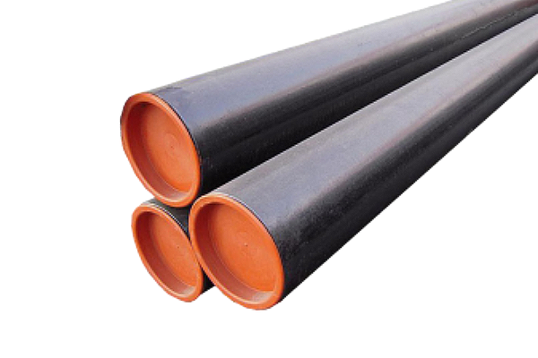
This standard is commonly used in the construction of steel structures, civil engineering, and the installation of oil, gas, water or electricity pipelines.

Why Choose Us?

EN 10219 Steel Grade

Black_iron_pipe_VS_black_steel_pipe_carbon_steel_pipe_manufacturing

S235JRH

  • Yield strength: ≥235 MPa
  • Impact toughness: 27J @ 0°C
  • Application: Commonly used in building frames, machinery manufacturing, bridges and infrastructure, etc.
types of steel-carbon steel

S355J0H

  • Yield strength: ≥355 MPa
  • Impact toughness: 27J @ 0°C
  • Application: Used in high-rise building structures or mechanical equipment that require high strength and high stability.
ERW_pipe_supplier_carbon_steel_pipe_UNIASEN

S275J0H

  • Yield strength: ≥275 MPa
  • Impact toughness: 27J @ 0°C
  • Application: Commonly used in medium-strength structural engineering, such as stairs, railings and small and medium-sized building structures.
Understanding Schedule 80 Steel Pipes

S355J2H

  • Yield strength: ≥355 MPa
  • Impact toughness: 27J @ -20°C
  • Application: Suitable for high-strength structures that need to work in low-temperature environments.
Natural Gas Pipeline Project in Xinjiang City, China-UNIASEN carbon steel pipe project

S275J2H

  • Yield strength: ≥275 MPa
  • Impact toughness: 27J @ -20°C
  • Application: It has the same strength as S275J0H, but is more suitable for working in low temperature environments.

S355K2H

  • Yield strength: ≥355 MPa
  • Impact toughness: 27J @ -20°C
  • Application: Its strength is the same as S355J2H, but it is more suitable for use in low temperature environments.

Specification of EN 10219

STANDARD EN 10219
Procedure ERW
Dimensions 21.3mm – 1219mm
20×20-400×400mm
40×20-480×240mm
Thickness 2.0mm – 40mm
3 – 18 mtrs
Unit Length 2.4 – 11.6m
Steel Grade S235JRH, S355J0H, S275J0H, S355J2H, S275J2H, S355K2H
Surface Coating Black lacquer coating and Hot-Dipped Zinc-Coated (Galvanized), FBE 3PE 3PP
End Type Plain, Bevelled, Threaded, Grooved, Shouldered
Joint Method Fitting, Flange, Coupling, Clamp, Pipe Shoulder, Welding
Pipe Machining Welding, Bending, Hole Drilling, Punching, Swaging, Tapering, Flaring, Expanding

EN 10219 Dimensions And Sizes

Each size is precisely calibrated to EN 10219 standards, ensuring our pipes perform optimally in a wide range of applications.

Outside
Diameter
(mm)
Nominal Dimensions Of a Limited Range Of Circular Hollow Sections
(mm)
21.3 2.0 2.5 3.0
26.9 2.0 2.5 3.0
33.7 2.0 2.5 3.0
42.4 2.0 2.5 3.0 4.0
48.3 2.0 2.5 3.0 4.0 5.0
60.3 2.0 2.5 3.0 4.0 5.0
76.1 2.0 2.5 3.0 4.0 5.0 6.0 6.3
88.9 2.0 2.5 3.0 4.0 5.0 6.0 6.3
101.6 2.0 2.5 3.0 4.0 5.0 6.0 6.3
114.3 2.0 2.5 3.0 4.0 5.0 6.0 6.3
139.7 3.0 4.0 5.0 6.0 6.3 8.0 10.0
168.3 3.0 4.0 5.0 6.0 6.3 8.0 10.0
177.8 4.0 5.0 6.0 6.3 8.0 10.0 12.0 12.5
193.7 4.0 5.0 6.0 6.3 8.0 10.0 12.0 12.5
219.1 4.0 5.0 6.0 6.3 8.0 10.0 12.0 12.5
244.5 5.0 6.0 6.3 8.0 10.0 12.0 12.5
273.0 5.0 6.0 6.3 8.0 10.0 12.0 12.5
323.9 5.0 6.0 6.3 8.0 10.0 12.0 12.5
355.6 5.0 6.0 6.3 8.0 10.0 12.0 12.5 16.0 20.0
406.4 6.0 6.3 8.0 10.0 12.0 12.5 16.0 20.0 25.0
457 6.0 6.3 8.0 10.0 12.0 12.5 16.0 20.0 25.0 30.0
508 6.0 6.3 8.0 10.0 12.0 12.5 16.0 20.0 25.0 30.0
610 6.0 6.3 8.0 10.0 12.0 12.5 16.0 20.0 25.0 30.0
711 6.0 6.3 8.0 10.0 12.0 12.5 16.0 20.0 25.0 30.0
762 6.0 6.3 8.0 10.0 12.0 12.5 16.0 20.0 25.0 30.0
813 8.0 10.0 12.0 12.5 16.0 20.0 25.0 30.0
914 8.0 10.0 12.0 12.5 16.0 20.0 25.0 30.0
1016 8.0 10.0 12.0 12.5 16.0 20.0 25.0 30.0
1067 10.0 12.0 12.5 16.0 20.0 25.0 30.0
1168 10.0 12.0 12.5 16.0 20.0 25.0
1219 10.0 12.0 12.5 16.0 20.0 25.0
Other sizes and thicknesses within the scope of this standard may be available.
Outside diameters up to 2 500 mm, wall thicknesses up to 40 mm.
Specified side dimension
(mm)
Nominal Dimensions Of a Limited Range Of Square Hollow Sections
(mm)
20 2.0
25 2.0 2.5 3.0
30 2.0 2.5 3.0
40 2.0 2.5 3.0 4.0
50 2.0 2.5 3.0 4.0 5.0
60 2.0 2.5 3.0 4.0 5.0 6.0 6.3
70 2.5 3.0 4.0 5.0 6.0 6.3
80 3.0 4.0 5.0 6.0 6.3 8.0
90 3.0 4.0 5.0 6.0 6.3 8.0
100 3.0 4.0 5.0 6.0 6.3 8.0 10.0 12.0 12.5
120 3.0 4.0 5.0 6.0 6.3 8.0 10.0 12.0 12.5
140 4.0 5.0 6.0 6.3 8.0 10.0 12.0 12.5
150 4.0 5.0 6.0 6.3 8.0 10.0 12.0 12.5 16.0
160 4.0 5.0 6.0 6.3 8.0 10.0 12.0 12.5 16.0
180 4.0 5.0 6.0 6.3 8.0 10.0 12.0 12.5 16.0
200 4.0 5.0 6.0 6.3 8.0 10.0 12.0 12.5 16.0
220 5.0 6.0 6.3 8.0 10.0 12.0 12.5 16.0
250 5.0 6.0 6.3 8.0 10.0 12.0 12.5 16.0
260 6.0 6.3 8.0 10.0 12.0 12.5 16.0
300 6.0 6.3 8.0 10.0 12.0 12.5 16.0
350 8.0 10.0 12.0 12.5 16.0
400 10.0 12.0 12.5 16.0
Other sizes and thicknesses within the scope of this standard may be available.
Outside dimensions up to 500 mm × 500 mm, wall thicknesses up to 40 mm.
Specified Side Dimensions
(mm)
Nominal Dimensions Of a Limited Range Of Square Hollow Sections
(mm)
40 20 2.0 2.5 3.0
50 30 2.0 2.5 3.0 4.0
60 40 2.0 2.5 3.0 4.0 5.0
70 50 2.0 2.5 3.0 4.0 5.0
80 40 2.0 2.5 3.0 4.0 5.0
80 60 2.0 2.5 3.0 4.0 5.0
90 50 2.0 2.5 3.0 4.0 5.0
100 40 2.5 3.0 4.0 5.0
100 50 2.5 3.0 4.0 5.0 6.0 6.3
100 60 2.5 3.0 4.0 5.0 6.0 6.3
100 80 2.5 3.0 4.0 5.0 6.0 6.3
120 60 2.5 3.0 4.0 5.0 6.0 6.3 8.0
120 80 3.0 4.0 5.0 6.0 6.3 8.0
140 80 4.0 5.0 6.0 6.3 8.0
150 100 4.0 5.0 6.0 6.3 8.0 10.0 12.0 12.5
160 80 4.0 5.0 6.0 6.3 8.0 10.0 12.0 12.5
180 100 4.0 5.0 6.0 6.3 8.0 10.0 12.0 12.5
200 100 4.0 5.0 6.0 6.3 8.0 10.0 12.0 12.5
200 120 4.0 5.0 6.0 6.3 8.0 10.0 12.0 12.5
250 150 5.0 6.0 6.3 8.0 10.0 12.0 12.5 16.0
260 180 5.0 6.3 8.0 10.0 12.0 12.5 16.0
300 100 6.0 6.3 8.0 10.0 12.0 12.5 16.0
300 150 6.0 6.3 8.0 10.0 12.0 12.5 16.0
300 200 6.0 6.3 8.0 10.0 12.0 12.5 16.0
300 250 6.0 6.3 8.0 10.0 12.0 12.5 16.0
400 200 8.0 12.5 16.0
400 300 8.0 10.0 12.0 12.5 16.0
Other sizes and thicknesses within the scope of this standard may be available.
Outside dimensions up to 500 mm × 300 mm, wall thicknesses up to 40 mm

Chemical Requirement

The following are the chemical composition requirements for EN 10219 hollow structural pipes.

Chemical Composition — Cast Analyses For Product Thicknesses ≤40 Mm, Feedstock Condition N  a
Steel grade Type of
deoxidation
b
Classification
c
% by mass
Steel name Steel number C
max.
Si
max.
Mn P
max.
S
max.
Nb
max.
V
max.
Al total d
min.
Ti
max.
Cr
max.
Ni
max.
Mo
max.
Cu e
max.
N
max.
S275NH 1.0493 GF QS 0.20 0.40 0.50- 1.40 0.035 0.030 0.050 0.05 0.020 0.03 0.30 0.30 0.10 0.35 0.015
S275NLH 1.0497 0.030 0.025
S355NH 1.0539 GF QS 0.20 0.50 0.90- 1.65 0.035 0.030 0.050 0.12 0.020 0.03 0.30 0.50 0.10 0.35 0.015
S355NLH 1.0549 0.18 0.030 0.025
S460NH 1.8953 GF SS 0.20 0.60 1.00- 1.70 0.035 0.030 0.050 0.20 0.020 0.03 0.30 0.80 0.10 0.70 0.025
S460NLH 1.8956 0.030 0.025
a    See 6.3.
b    The deoxidation method is designated as follows:
GF = Fully killed steel containing nitrogen binding elements in amounts sufficient to bind the available nitrogen and having a fine grained structure.
c    QS = quality steel; SS = special steel.
d     If sufficient N-binding elements are present, the minimum total Al content does not apply.
e     If the copper  content is greater than 0.30 % then the nickel content shall be at least half of the copper content.
Chemical Composition – Cast Analysis For Product Thicknesses ≤ 40 Mm, Feedstock Condition M a
Steel Grade Type of Deoxidation b   Classification c % by Mass
Steel Name Steel Number C
max.
Si
max.
Mn
max.
P max. S max. Nb
max.
V
max.
Al total d
min.
Ti max. Ni max. Mo e
max.
N max.
S275MH 1.8843 GF SS 0,13 0,50 1,50 0,035 0,030 0,050 0,08 0,020 0,050 0,30 0,20 0,020
S275MLH 1.8844 0,030 0,025
S355MH 1.8845 GF SS 0,14 0,50 1,50 0,035 0,030 0,050 0,10 0,020 0,050 0,30 0,20 0,020
S355MLH 1.8846 0,030 0,025
S420MH 1.8847 GF SS 0,16 0,50 1,70 0,035 0,030 0,050 0,12 0,020 0,050 0,30 0,20 0,020
S420MLH 1.8848 0,030 0,025
S460MH 1.8849 GF SS 0,16 0,60 1,70 0,035 0,030 0,050 0,12 0,020 0,050 0,30 0,20 0,025
S460MLH 1.885 0,030 0,025
a    See 6.3.
b    The deoxidation method is designated as follows:
GF = Fully killed steel containing nitrogen binding elements in amounts sufficient to bind the available nitrogen and having a fine grained structure.
c    SS = special steel.
d    If sufficient N-binding elements are present, the minimum total Al content does not apply.
e    The total sum of Cr, Cu and Mo shall not be higher than 0,60 %.
Maximum Carbon Equivalent Value Based On Cast Analysis
Steel Grade Maximum CEV for Nominal
Thicknesses ≤ 40 mm
%
Steel Name Steel Number
S275NH
S275NLH
 1.0493
1.0497
0.40
S275MH
S275MLH
  1.8843
1.8844
0.34
S355NH
S355NLH
  1.0539
1.0549
0.43
S355MH
S355MLH
  1.8845
1.8846
0.39
S420MH
S420MLH
  1.8847
1.8848
0.43
S460NH
S460NLH
  1.8953
1.8956
0.53
S460MH
S460MLH
  1.8849
1.8850
0.46

Mechanical Requirement

The following are the mechanical requirements for hollow structural pipes according to EN 10219.

Mechanical Properties Of Hollow Sections In Thicknesses ≤ 40 Mm — Feedstock Material Condition N
Steel Grade Minimum Yield
Strength ReH

MPa

Tensile
Strength Rm

MPa

Minimum
Elongation A
a b
%
Minimum Impact Energy KV c

J

Steel Name   Steel Number
Specified
Thickness
mm
Specified
Thickness
mm
Specified
Thickness
mm
at Test Temperature of
≤ 16 > 16 ≤ 40 ≤ 40 ≤ 40 -50 °C -20 °C
S275NH   1.0493 275 265 370-510 24 40 d
S275NLH   1.0497 27
S355NH   1.0539 355 345 470-630 22 40 d
S355NLH   1.0549 27
S460NH   1.8953 460 440 540-720 17 40 d
S460NLH   1.8956 27
a    For section sizes D/T < 15 (circular) and (B+H)/2T < 12,5 (square and rectangular) the minimum elongation is reduced by 2.
b    For thicknesses < 3 mm see 9.2.2.
c    For impact properties for reduced section test pieces see 6.7.2.
d    This value corresponds to 27J at –30 °C (see EN 1993-1-1).
Mechanical Properties Of Hollow Sections In Thicknesses ≤ 40 Mm — Feedstock Material Condition M
Steel Grade Minimum Yield
Strength ReH

MPa

Tensile
Strength Rm

MPa

Minimum
Elongation A
a b
%
Minimum Impact Energy KV c

J

Steel Name   Steel Number
Specified
Thickness
mm
Specified
Thickness
mm
Specified
Thickness
mm
at Test Temperature of
≤ 16 > 16 ≤ 40 ≤ 40 ≤ 40 -50 °C -20 °C
S275MH   1.8843 275 265 360-510 24 40 d
S275MLH   1.8844 27
S355MH   1.8845 355 345 450-610 22 40 d
S355MLH   1.8846 27
S420MH   1.8847 420 400 500-660 19 40 d
S420MLH   1.8848 27
S460MH   1.8849 460 440 530-720 17 40 d
S460MLH   1.8850 27
a    For section sizes D/T < 15 (circular) and (B+H)/2T < 12,5 (square and rectangular) the minimum elongation is reduced by 2.
b    For thicknesses < 3 mm see 9.2.2.
c    For impact properties for reduced section test pieces see 6.7.2.
d    This value corresponds to 27J at –30 °C (see EN 1993-1-1).
China ERW Pipe manufacturer

Welded Pipe

ssaw steel pipe manufacturer and supplier

SSAW Steel Pipe

steel hollow section-hollow structural section-Uniasen

Hollow Structural Section

seamless steel pipe-SMLS Pipe

Seamless Steel Pipe

china pipe fitting-carbon steel pipe fittings

Pipe Fittings Pipe Fittings

Fire Sprinkler Pipe

Line Pipe

ASTM A106 Seamless Steel Pipe